 bermansplaining
/blog/from-concept-art-to-a-working-robot-head
Embodied AI: DIY Hobby Robotics · Part 2
From Concept Art to a Working Robot Head
Machinic desire can seem a little inhuman, as it rips up political cultures, deletes traditions, dissolves subjectivities, and hacks through security apparatuses, tracking a soulless tropism to zero control. This is because what appears to humanity as the history of capitalism is an invasion from the future by an artificial intelligent space that must assemble itself entirely from its enemy’s resources.
— Nick Land, Fanged Noumena: Collected Writings, 1987–2007
When I last left off, ChatGPT (running 6.1 Sol), Claude Opus 5.5 (through Claude Code) and I had begun planning an AI robotic companion that gives my agents a body, plus some quality-of-life tools for my workstations: a camera, speech in a custom voice of my choosing, and another interface for keeping track of agent progress.
From there we landed on a 90s anime mecha-inspired character and a set of affordable but effective parts, which I list below. With those parts, ChatGPT and Claude’s guidance, and a little trial and error with my 3D printer, we’ve built a (hopefully) well-engineered head carrier. Mounted in it are the screen (which will double as my companion’s face and as the display for everything plugged into the Raspberry Pi 5) and the camera we chose. I also got initial software running to test the face design and emotions on the 5-inch screen, and to check how legible those emotions actually are.
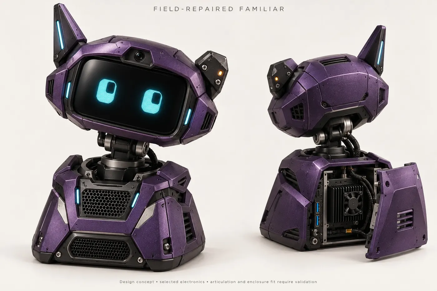
Chapter 1: Why I Wanted a Familiar
Honestly, AI wasn’t immediately useful to me, as I don’t code for a living, nor do I have a job where I can trust an LLM to write for me. I come from the mindset that being an attorney is effectively a customer service job, with the differentiators being your writing and speaking ability (honestly, you only need one to be successful, and the two are often mutually exclusive).
That being said, the value I’ve gotten from AI came from hobby use, where I’ve tried to create tools and instruments that help with my personal life (the obvious habit tracking and general knowledge stuff). But the more time I spend with language models, the more I find the otherwise impressive Qwen 3.8 27B anemic on the social front, and all Claude models increasingly annoying to actually talk to. Chat is okay, but I still keep my distance outside of more personalized harnesses like Hermes. I also find switching to my phone to take pictures and upload media annoying, and plugging sensors into my gaming PC or laptop doesn’t solve that device-to-device swapping problem either.
And thus the AI companion familiar/robot came into existence. One of the most unpleasant aspects of my favorite hobby (reading) is note-taking. Maybe that’s ironic coming from an attorney who survived seven years of university (or maybe it’s a perfectly rational trauma response), but I no longer enjoy highlighting, or re-logging notes and quotes while I read. It breaks up my reading flow and means I make less progress than I’d like.
This led me to my ideal AI companion: one that keeps track of the book I’m currently reading and, equipped with cameras, mics and speakers, lets me read off the quotes, sections or ideas I want to save and return to later, then logs them to Obsidian or any other centralized database of mine. If I don’t want to read something out loud, I can show the book to the camera and ask it to retain the info. If I come across a design, an illustration or anything else I’d like to keep for inspiration, I can show it to the companion, which, again through the agent, saves it to my centralized database. If I change agents, models or devices later, the database stays, and I don’t suffer for upgrading.
That’s just one feature, alongside the agent-management workflow I covered in the last post, and once the companion exists I’ll use it to keep experimenting with ideas and tools for an embodied AI that I haven’t even thought of yet. Philosophically, this ontology is exciting, and more in line with my workflow than endless terminals and tmux lol.
It also lets me play with robotics, a domain that has always interested me, but where the off-the-shelf options felt generic and never scratched my customization itch. A modular companion I can upgrade, repair, and eventually give siblings is a different story. Even the design process opened up visual storytelling and a backstory for the companion, which in turn fed ideas for features. To me, this is the most underappreciated thing about AI tools, by anti-AI advocates and normal users alike: premium frontier models give you a personalized education that literally matches your knowledge level, resources, and goals.
Enough of the concept. Here’s the hardware:
Chapter 2: Choosing and Testing the Hardware
| Part | Build inventory and status |
|---|---|
| Raspberry Pi 5 | 8GB CanaKit kit and 128GB microSD; local device interface and face display. Pi and display have run on the bench. |
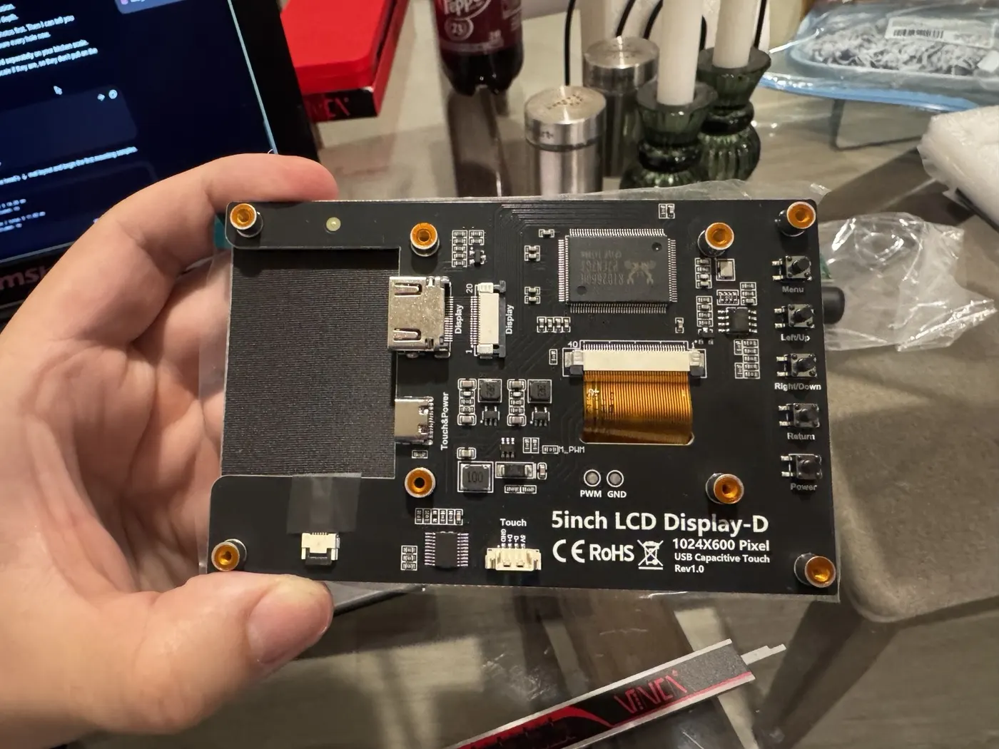
| Face display | ELECROW five-inch 1024 x 600 touchscreen. Chosen over the earlier 3.5-inch and 4.3-inch candidates because the price was basically the same, and the bigger screen has more dual-purpose potential beyond just the face. |
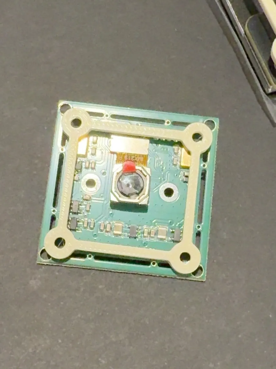
| Camera | Arducam USB camera; received rear board marking UC-626 Rev.C. Live video tested, including after mounting on the Pi. |
| Audio | Seeed reSpeaker XVF3800 USB four-mic array plus one Seeed Studio Mono Enclosed Speaker (4 Ω / 5 W). Recording and playback worked in the PC bench tests. |
| Desktop AI host | My existing RTX 5090 PC, intended for the substantial AI workloads. A finished agent-to-robot bridge is still future work. |
| Printing | Bambu Lab P1S for the prototype mounts and carrier. Exterior armor is a later fabrication stage. |
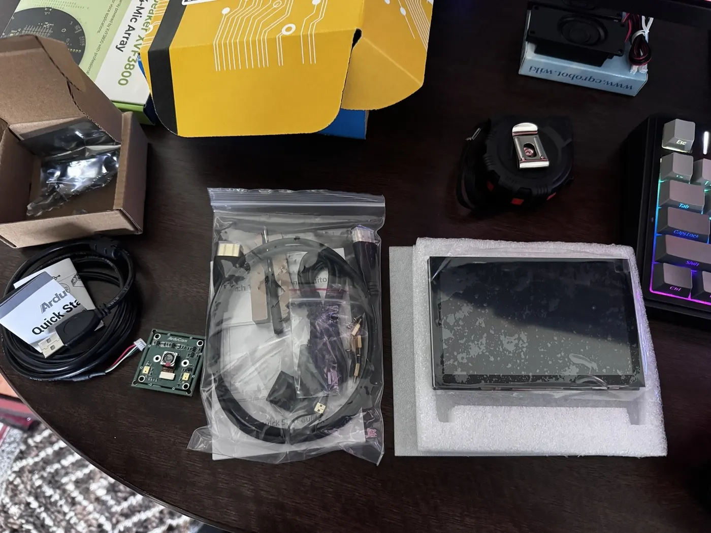
This was honestly the part that concerned me most, and its successful outcome is what gave me the confidence to keep going. Generating mockups is one thing, but building a 3D-printed robot out of various parts ordered online left me skeptical. Again, I wasn’t following any particular guide or tutorial. Instead, I let both frontier models take the wheel and bounce engineering ideas off each other while I gave feedback and thoughts, and the parts list manifested.
Being an AI optimist, I pulled the trigger, ordered all the parts, and let the models engineer the head frame below.
Chapter 3: Turning Measurements Into Fit Prints
At this point I had all the parts and had tested that they all worked, but I was genuinely having trouble visualizing how they would mount together with clean cable management. Turns out I should have just trusted the plan.
With some calipers, I measured the screen and camera, their mounting patterns, lens sizes and locations, and the dimensions and weight of all the plugs (weighed on a food scale at home lol). The head envelope needed more than just the advertised diagonal screen size, and these millimeter measurements let Claude create hyper-accurate CAD files for 3D printing. Chat and Claude together came up with some good ideas on cable clearance and how to fit the head together, and we went through four iterations of the head. I’ll share the final files once I know the neck and torso all work.
| Part | Reported dimensions | Reported mass |
|---|---|---|
| Screen | 120.97 x 77.06 x 14.26 mm | 111 g without cables |
| Camera | 38.14 x 38.16 x 11.62 mm | 6 g without cable |
As we iterated, my favorite thing was that Chat and Claude would design small test prints that checked just one part of the mount, confirming fit, screw sizes, etc., without needing to print the entire thing each time.
Every time I felt dumb or out of my depth, I could just start a new chat within the project, ask it to ELI5, and get the help I needed. Again, a GOATed part of this whole process is learning about different systems along the way through hands-on tasks.
Chapter 4: Building the V4 Internal Carrier
By V4 we had a pretty snazzy internal head carrier, which not only fit all the parts securely, but also allowed for legit cable clearance for the next, and possibly more important, step: the neck.
Getting there wasn’t clean: in V1 through V3, the feet and tabs just didn’t fit. But the iteration process was super quick. If Chat and Claude recommended screw holes of a specific size, I pushed back whenever the real world didn’t comply. My favorite change request was asking for parts I could snap or tab together, and the best addition there was slots in the screen frame that perfectly fit washers to better hold the mounting screws.
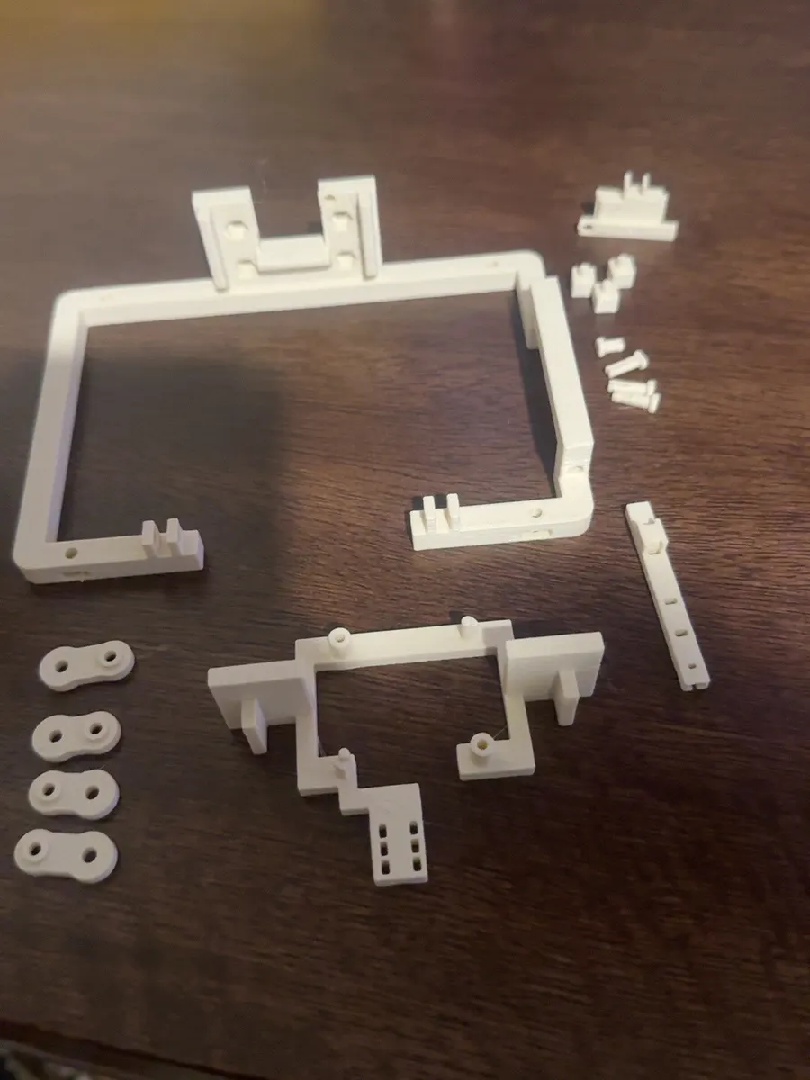
All told, the V4 internal carrier came out to twelve printed pieces: the frame, camera bracket, four screen tabs, the gate bar, passage lid and four locking pins.
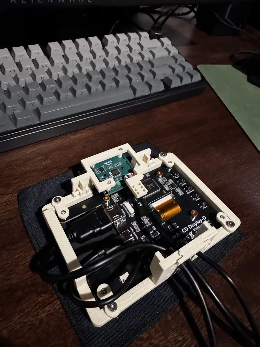
Once everything was mounted, I could finally visualize the cable routing, and I realized how good a job the agents had done engineering this thing.
Chapter 5: Making Room for the Cables
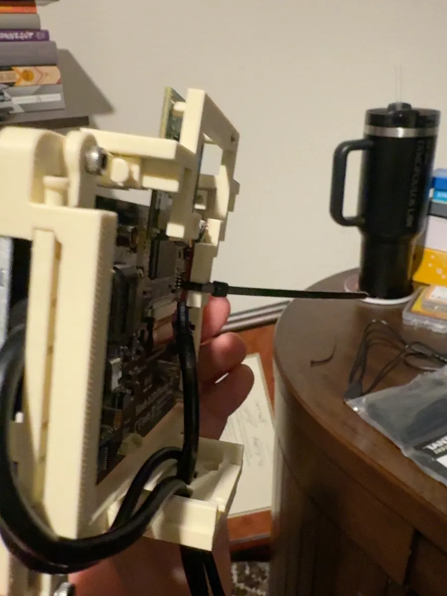
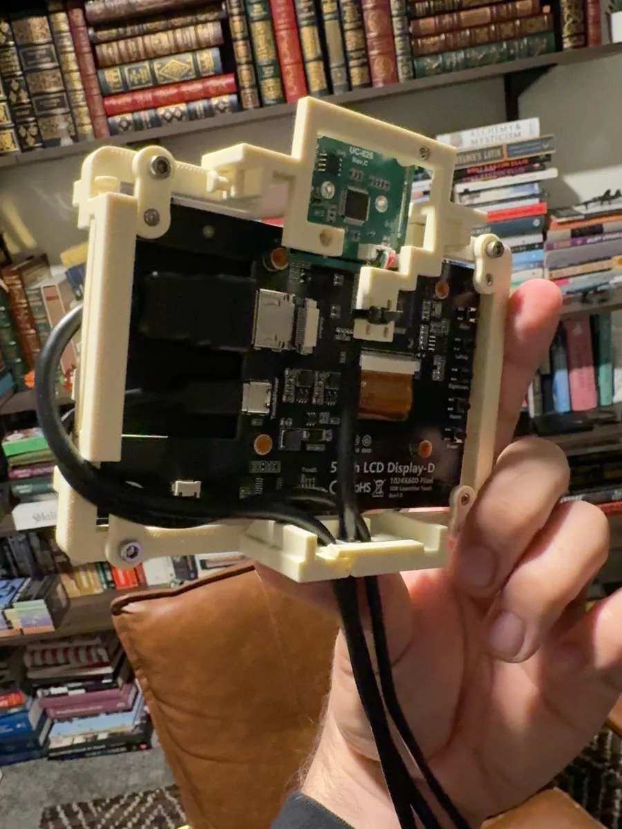
You can see from the side-view photos that the head carrier needed more depth than we initially planned for, to make room for the thicker full-size HDMI plug as well as the USB and camera connectors.
Once the cables were routed, we could start visualizing what the neck stage would require. On one hand, we were pleased with how snugly the cables fit; on the other, we want to make sure neck movement isn’t going to damage anything once we know how much slack we have.
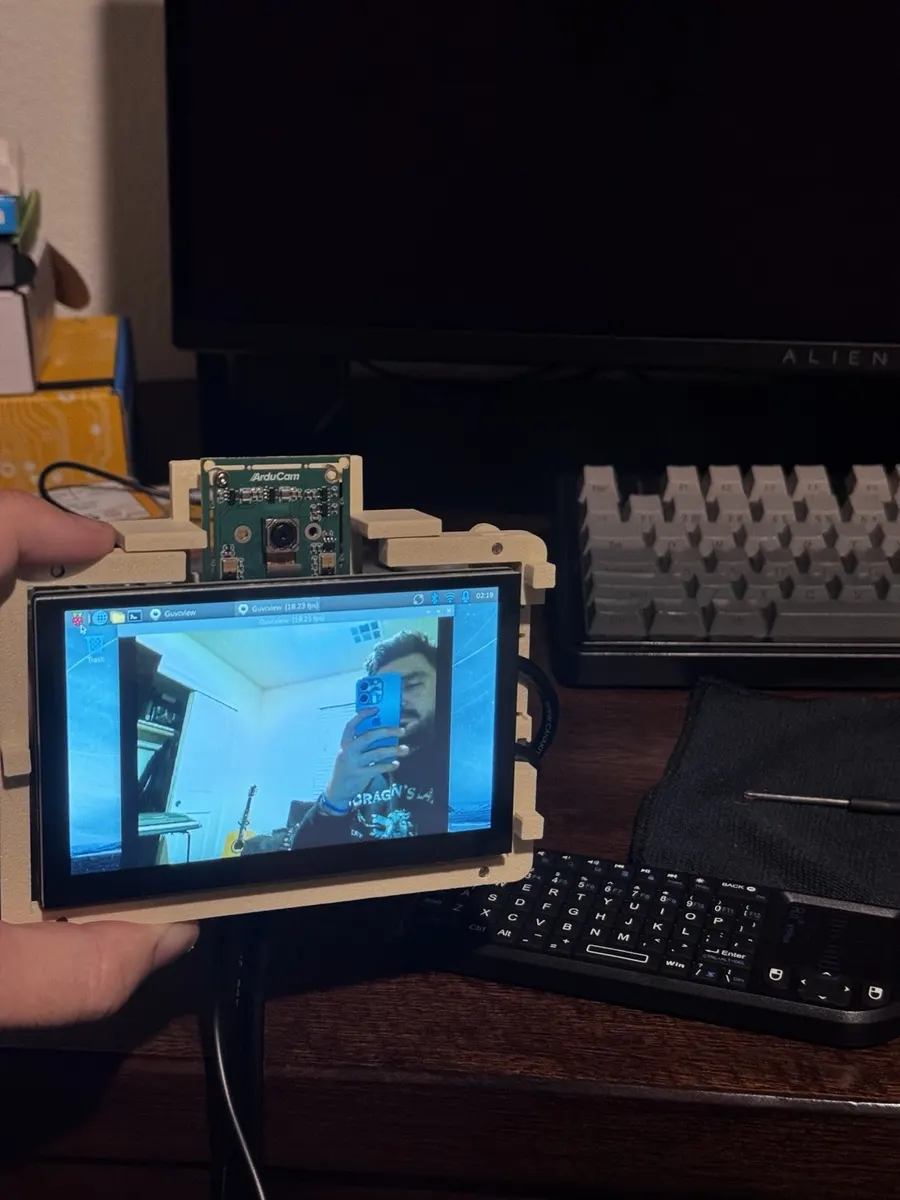
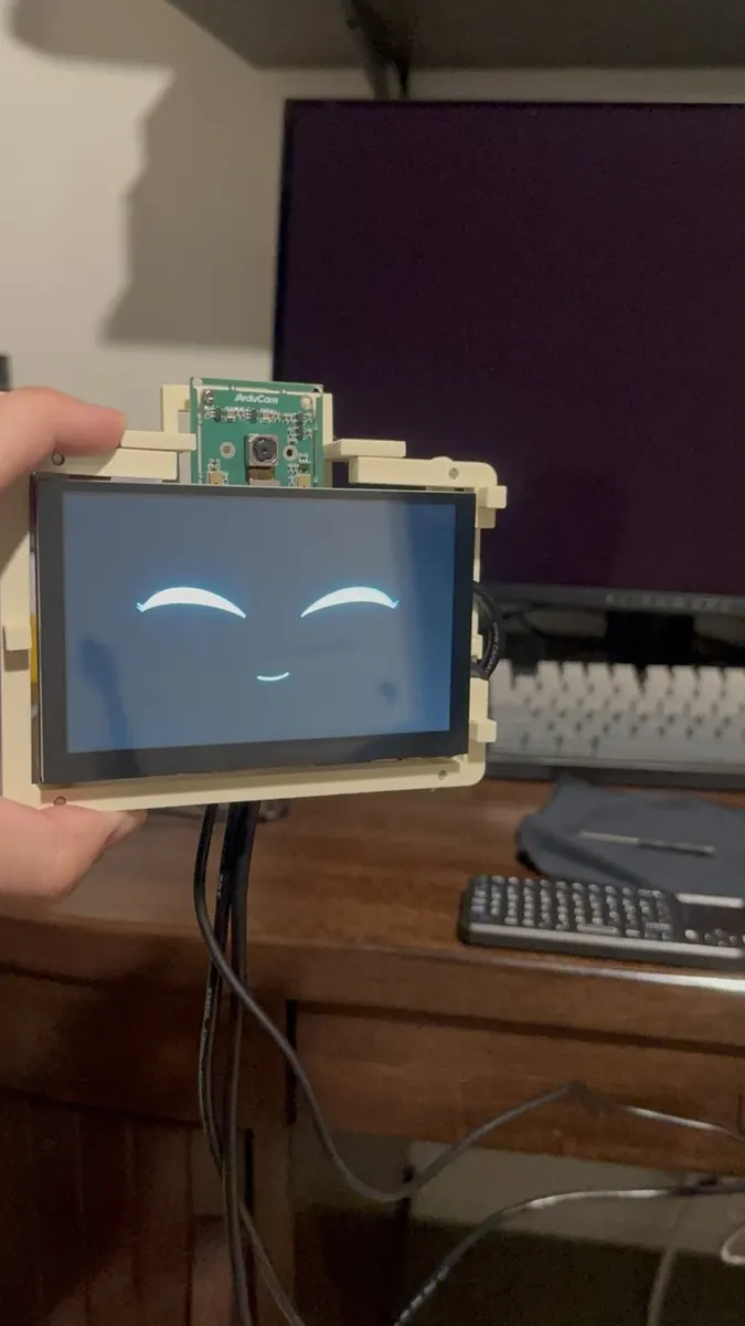
Chapter 6: Seeing the Head Work on the Pi
With the head assembled, I re-tested the face software on the screen for visibility and legibility in the actual setup. It was cool seeing the camera and screen working together, and honestly it inspired some ideas for the later cyberdeck design.
For the face, I’m vacillating between something entirely digital and robotic and something warmer and more human. I think before I finalize the software, I’ll have to see the final shell and coloring so I can compare the face design to the body itself. That’s something I didn’t contemplate going in, and it’s a good example of how the embodied AI itself will inspire continued design iterations.
Chapter 7: The Checkpoint Before the Neck
| Area | Checkpoint |
|---|---|
| Working on the bench | Pi and display; mounted face rendering; live camera preview. Microphone recording and speaker playback passed separate PC tests. |
| Measured | Current screen, camera, carrier and the cables placed on the scale: 284 g. |
| Next mechanical work | A supported three-axis neck for turning, nodding and tilting, followed by the exterior shell and torso packaging. |
| Later software work | Agent bridge, conversational behavior, and coordinated face, speech and movement. |
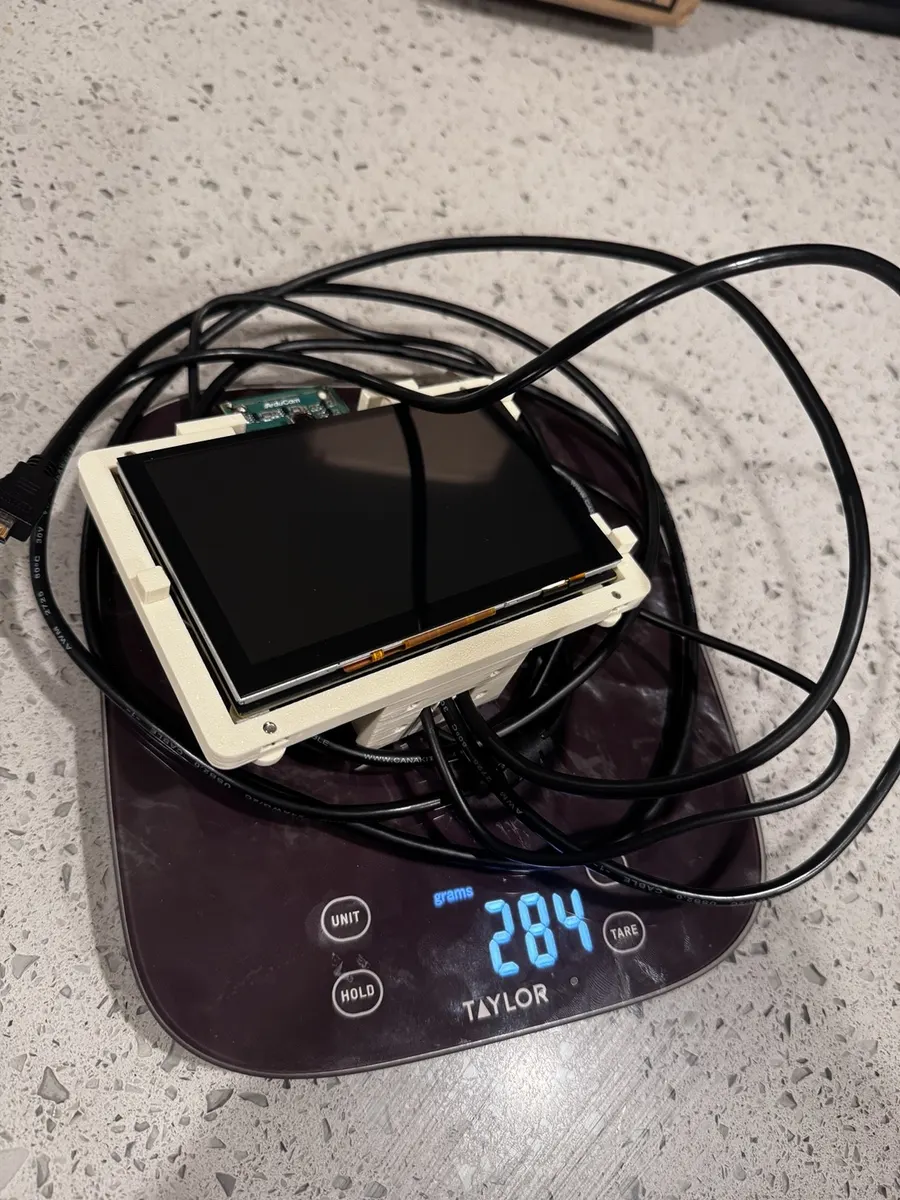
That 284 g is the number that matters most going into the neck. Every gram up here is weight the neck motors have to lift, turn and hold steady, and the farther that weight sits from the pivot, the harder they have to work. So the head’s weight (plus whatever the armor adds later) basically decides how strong, and how expensive, the motors need to be: too weak and the head sags or jitters every time it nods, too strong and the neck gets bulky and eats into the space and budget for everything else. Back on the food scale it went lol.
What the head cost
If you’re wondering what this costs so far, here’s everything in the head as of this checkpoint. Prices are estimates of what I paid, before tax and shipping, and a pack price covers the whole pack even if only a piece or two made it into the robot. The audio hardware and the neck parts get their own list next post.
| Part | Est. price | Qty | Source | Notes |
|---|---|---|---|---|
| 5-inch HDMI capacitive touch display | $40.00 | 1 | Amazon | 1024 x 600; rear label reads 5inch LCD Display-D. Full-size HDMI at the display. |
| Arducam USB camera board | $25.00 | 1 | Amazon | PCB marking UC-626 Rev.C. Installed and tested. |
| Camera USB lead | Included | 1 | Camera kit | Small board plug to USB-A at the Pi. |
| Display HDMI lead | Included | 1 | CanaKit Pi kit | Full-size HDMI at the display, micro-HDMI at the Pi. |
| Display USB power/touch lead | $7.00 | 1 | Existing cable stock | USB-C at the display, USB-A at the Pi. |
| V4 printed carrier parts, plus reused V3a feet | — | 1 set | Printed on the Bambu P1S | Frame, camera bracket, four screen tabs, gate bar, passage lid and four lock pins. |
| M2.5 screen screws and pillars | Included | 1 set | Included with the display | Short screws at the four screen tabs. |
| M2/M3 screw assortments | $16.00 | Assorted | Amazon | Carrier and camera fastening hardware; combined kit price. |
| Cable-tie kit | $5.00 | 1 tie used | Amazon | Holds the camera lead in place. |
| CanaKit Raspberry Pi 5 starter kit | $260.00 | 1 | Amazon | Pi 5 8 GB, 128 GB microSD, case, cooling and power supply. Moves into the torso later. |
| Total | $353.00 | $93 without the Pi kit. |
What’s Next?
At this checkpoint, I have a working head carrier, a clean cable layout (that hopefully survives the moving-neck stage), and the Pi brain up and running, connected to the screen.
I leave this checkpoint with an insanely heightened trust in frontier models to engineer things that carry over into the physical world. Much like hiring a real engineer, I love the feeling of exerting my agency over the project while the model’s “guide” style instructions adapt to my needs and decisions.
Next up is the neck, which I’ve already begun ideating with both ChatGPT and Claude and will finalize this weekend.